Logic Gates (AND, OR, NOT Gates) Part 1/2
In this video, I will explain the working principle of logic gates that form the basis of all electronic devices we use, which we can encounter in many areas in daily life. When we say digital electronics, the first thing that comes to our mind is logic gates. When numerical expressions are mentioned, level 1, level 0, logic circuits or in other words logic gates come to mind. This type of integrated circuit consists of circuits made with basic electronic elements such as transistors, resistors and diodes.
Logic gates form the basis of digital systems. Input information is transferred to the output by performing Boolean mathematics operations. Operations are performed on the logical expressions Logic-1 and Logic-0. The reciprocal of 1 logic expression is defined as 5V, and the reciprocal of 0 logic expression is defined as 0V.
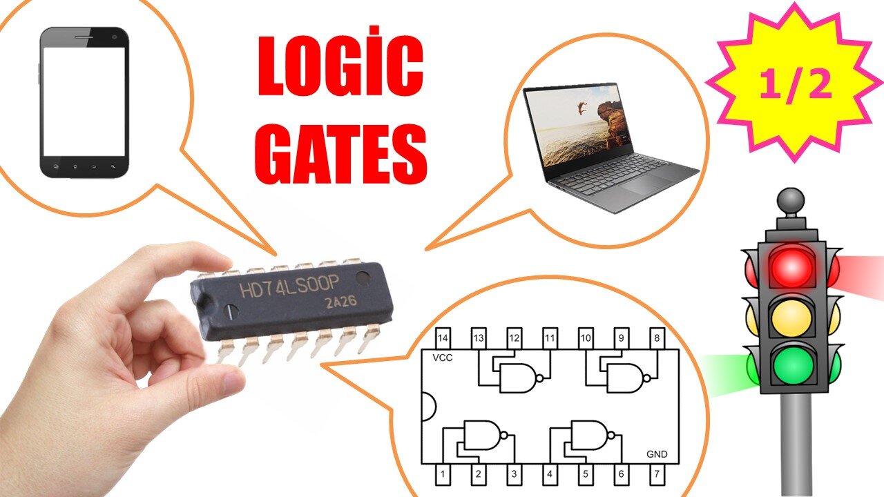
Now let's look at how to number the pins of the logic gates. When we hold it to read the text on the IC, there is a notch on the left side. The pins are numbered starting from this notch. Logic gate ICs are generally 14 pins.
For example, when we look at the internal structure of the 7408 IC, we see that it consists of four AND gates. This logic gate has two inputs and one output. When we go into a little more detail and look inside an AND gate, we see that there is a circuit consisting of two BJT transistors and resistors.
There are 7 types of basic logic gate circuits: They are the AND gate, OR gate, NOT gate, NAND gate, NOR gate, XOR gate, and finally the XNOR gate. These circuits, also known as logic gates, produce appropriate logical results with 1 and 0 data received from the input, namely 5V and 0V, within a certain Boolean Algebra framework. That is why we can say that they are indispensable elements of digital electronic systems. Now, let's examine the symbols, mathematical expressions and truth tables of these logic gates one by one. In order for the video not to be too long and boring, I will explain the AND, OR and NOT gates in this video. In the next video, I will explain other logic gates.
00:00 Introductor
02:29 AND Gate
04:55 OR Gate
06:40 NOT Gate
#logic #gates #electronics
-
 6:26
6:26
Electrical Electronics Applications
2 years ago $0.04 earnedKirchhoff's Voltage Law (KVL) Explained
308 -
 1:48:49
Badlands Media
12 hours agoDevolution Power Hour Ep. 416: The Rug Pull Cycle, False Signals & Narrative Discipline
263K33 -
 1:06:11
Inverted World Live
11 hours agoA Ghost Ship in Washington, A Fire in Roswell | Ep. 155
66K4 -
 3:06:55
TimcastIRL
7 hours agoDan Bongino To RESIGN, Trump Addresses The Nation
345K433 -
 2:14:08
Barry Cunningham
6 hours agoLIVE BREAKING NEWS: President Trump Addresses The Nation! And More News!
55K20 -
 LIVE
LIVE
ThatStarWarsGirl
8 hours agoTSWG LIVE: Discussing STAR WARS News with Special Guest Star Wars Theory!
968 watching -
 2:42:40
Laura Loomer
6 hours agoEP162: LIVE: President Trump Addresses The Nation
56.2K26 -
 1:32:05
Adam Does Movies
11 hours ago $7.03 earnedRob Reiner Films + Movie News + AMA - Live!
32.1K1 -
 47:57
47:57
Professor Nez
10 hours ago🚨LIVE NOW: President Trump Addresses the Nation from the Oval Office
36.4K33 -
 28:17
28:17
The White House
7 hours agoPresident Trump Delivers an Address to the Nation
89.1K131