Premium Only Content

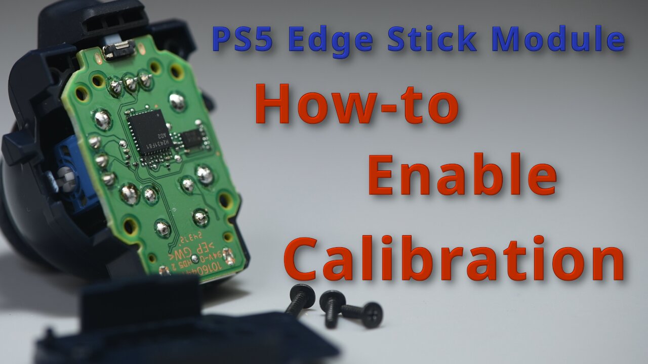
Ultimate Guide to Modifying DualSense Edge Stick Module for Calibration
In this video, I present a comprehensive guide to modifying the DualSense Edge stick module to enable calibration directly from the controller by writing to its memory chip. I break down the memory chip circuit within the module and highlight key circuit board contact points for each modification. The video covers multiple modification methods, including professional and no-solder options, with step-by-step explanations and a complete module schematic for reference.
Links:
Conductive Paint: https://a.co/d/a1PBjhw
Circuit Board Holder: https://a.co/d/17MosAx
DualSense Calibration Page: https://dualshock-tools.github.io/
Items used:
Soldering station: Hakko FX-951
Hot air station: Atten ST-862D
Solder wire: Kester 44 63/37 tin/lead 0.02 inch diameter
Solder paste: Kester EP256 63/37 tin/lead
Flux: Stirri STIRRI-V3-TF
4.7K Ohm 0201 Resistor: Yageo AC0201FR-074K7L
0 Ohm 0201 Resistor: Vishay CRCW02010000Z0ED
00:00 Introduction
00:25 Memory IC and Circuit Overview
02:28 Circuit Board Terminal Locations
04:10 Pro Modification
08:30 No-solder Modification
13:11 Force Pull-up Modification
17:50 Point to Point Modification
21:06 Important Modification Note
23:18 How to Open the Stick Module
24:15 Complete Module Schematic
-
 13:30
13:30
Metal Plastic Electronics
1 month ago $0.01 earnedAlps-Ginfull TMR Joysticks for PS5: The Ultimate Stick Drift Fix for Easy Repairs
6 -
 LIVE
LIVE
Lara Logan
7 hours agoTHE FIGHT FOR A FREE BRITAIN with Katie Hopkins | Episode 36 | Going Rogue with Lara Logan
680 watching -
 LIVE
LIVE
Jeff Ahern
50 minutes agoFriday Freak out with Jeff Ahern
116 watching -
 16:52
16:52
IsaacButterfield
10 hours ago $0.22 earnedWoke Karens Are Trying to End This Man’s Career
3.7K3 -
 4:09:14
The Bubba Army
1 day agoRaja Jackson Arrested! - Bubba the Love Sponge® Show | 9/19/25
13K2 -
 2:04:42
The Culture War with Tim Pool
4 hours agoDemonic Possession, Exorcisms, And The Soul Of America | The Culture War with Tim Pool
161K135 -
 20:00
20:00
Neil McCoy-Ward
2 hours ago🔥 It's Absolute CHAOS In Europe 🇪🇺 Today...
18.2K8 -
 1:07:41
Steven Crowder
4 hours agoSPECIAL: A Behind-the-Scenes Peek at Some of Our Biggest Productions
218K109 -
 59:40
59:40
The Rubin Report
4 hours agoListen to ‘The View’ Crowd Gasp as Whoopi Admits She Agrees w/ Conservatives on This
67.1K41 -
 1:40:02
The Mel K Show
3 hours agoMORNINGS WITH MEL K Preserving the Home of the Brave 9-19-25
46.4K5