IC 555 Timer in Monostable Mode | Working, Circuit, and Timing Formula Explained
IC 555 Timer in Monostable Mode | Working, Circuit, and Timing Formula Explained
https://electronics4ubymanmohanpal.blogspot.com/p/ic-555-monostable-mode.html
In this video, we’ll learn how the IC 555 Timer works in Monostable Mode — one of its most popular and useful configurations. You’ll understand the complete working principle, circuit diagram, timing formula, and practical applications with easy step-by-step explanation.
We’ll cover:
✅ What is Monostable Mode?
✅ How the 555 Timer generates a single pulse
✅ Working principle and waveform explanation
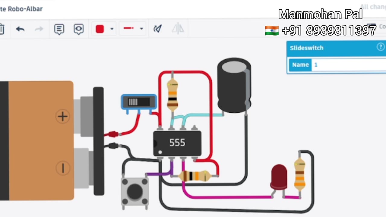
✅ Circuit diagram and component details
✅ Timing formula: T = 1.1 × R × C
✅ Real-time demonstration and calculation example
⚙️ Components Used:
IC 555 Timer
Resistor (R)
Capacitor (C)
Push Button (Trigger)
LED (Output indicator)
Breadboard & Jumper Wires
Power Supply (5V–12V)
📐 Timing Formula:
T = 1.1 × R × C
👉 Example: For R = 100 kΩ, C = 10 µF → T ≈ 1.1 seconds
💡 Applications:
Pulse generation
Switch debouncing
LED or buzzer timer
Delay circuits
Power-on reset delay
🔗 Watch Next:
🔹 IC 555 Astable Mode Explained
🔹 IC 555 Bistable Mode (Flip-Flop)
🔹 LED Blinker using IC 555
🧰 #Tags:
#IC555 #MonostableMode #ElectronicsProject #TimerCircuit #Arduino #ElectronicsBasics #555Timer #EngineeringProject #DIYElectronics
-
 LIVE
LIVE
Total Horse Channel
13 hours ago2025 IRCHA Derby & Horse Show - November 1st
77 watching -
 4:19
4:19
PistonPop-TV
6 days ago $3.81 earnedThe 4E-FTE: Toyota’s Smallest Turbo Monster
20.2K -
 43:07
43:07
WanderingWithWine
6 days ago $2.24 earned5 Dreamy Italian Houses You Can Own Now! Homes for Sale in Italy
16.5K3 -
 LIVE
LIVE
Spartan
21 hours agoFirst playthrough of First Berserker Khazan
217 watching -
 28:01
28:01
Living Your Wellness Life
2 days agoTrain Your Hormones
18.1K1 -
 43:28
43:28
The Heidi St. John Podcast
1 day agoFan Mail Friday: Faith Over Fear and Finding Strength in Every Season
10.1K -
 1:05:30
SGT Report
1 day agoTHE HORRIBLE TRUTH ABOUT EVERYTHING -- Harley Schlanger
52K93 -
 11:04
11:04
Blackstone Griddles
18 hours agoCountry Fried Steaks on the Blackstone Griddle
94.7K14 -
 49:47
49:47
Brad Owen Poker
1 day agoI Get My First BIIGGG Win! $25,000+ Buy-in! HORSE Championship! Don’t Miss! Poker Vlog Ep 324
18.3K1 -
 9:53
9:53
Rethinking the Dollar
1 day agoWhen Detroit Bleeds, America Suffer! Layoffs Have Begun
21.9K32